




What Does 303 Mean?
303 is not a secret code-it's the standard identity card of traffic signals.
In the traffic signal industry, product models follow a simple naming convention:
| Digit | Meaning | Explanation |
|---|---|---|
| First Digit | Lens diameter (mm) | 2=Φ200mm, 3=Φ300mm, 4=Φ400mm |
| Second Digit | Number of units | 0=single, 1=two units, 3=three units |
| Third Digit | Unit configuration | 3=three-unit (red + yellow + green) |
303 = 300mm lens diameter + three units (red + yellow + green)
This is the standard traffic signal configuration for urban intersections. When you see a 303 signal, you know exactly what it is: a 300mm diameter, red-yellow-green three-unit traffic signal, designed for motor vehicle lane direction control.
Two Common Types of 303 Signals
Based on the lens pattern, 303 signals come in two main types:
| Type | Pattern | Application |
|---|---|---|
| 303 Full Screen Signal | Solid circles (red circle + yellow circle + green circle) | Through lanes, mixed lanes, intersections without dedicated turn lanes |
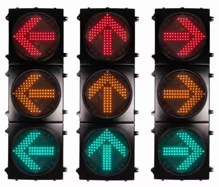
| 303 Arrow Signal | Arrow patterns (red arrow + yellow arrow + green arrow) | Dedicated left-turn lanes, dedicated right-turn lanes, intersections requiring clear direction indication |
How to distinguish:
Full screen: When green lights up, straight, left, and right turns are permitted (with yielding required)
Arrow signal: When green arrow lights up, only that direction is permitted-no conflict with other directions
Technical Specifications
Model Naming Code
| Parameter | Specification |
|---|---|
| Model Code | FX3003-XXX (Arrow) / DX3003-XXX (Full Screen) |
| Lens Diameter | Φ300mm (standard) |
| Standard Compliance | GB14887-2011 (National Standard) |
| Number of Units | 3 units (red + yellow + green) |
Optical Parameters
| Parameter | Red | Yellow | Green |
|---|---|---|---|
| LED Count | 144-270 pcs | 144-270 pcs | 144-270 pcs |
| LED Wavelength | 620-625nm | 589-595nm | 503-505nm |
| Luminous Intensity | 3000-5500mcd | 3000-5000mcd | 6000-10500mcd |
| LED Lifespan | ≥50,000-100,000 hours | ||
| Visibility Distance | ≥500m (daytime), ≥300m (night) | ||
| Viewing Angle | ≥30 degrees |
Electrical Parameters
| Parameter | Specification |
|---|---|
| Rated Voltage | AC176-264V, 50Hz / DC12V / DC24V |
| Single Unit Power | ≤10W-16W (energy-saving design) |
| Power Factor | >0.9 |
| Insulation Resistance | ≥500MΩ |
| Dielectric Strength | Withstands 1440VAC, 1 minute without breakdown |
Environmental & Mechanical Parameters
| Parameter | Specification |
|---|---|
| Housing Material | Die-cast aluminum / Polycarbonate (PC) |
| Surface Finish | Black powder coating, matte finish |
| Lens Cover Material | Tempered glass / PC |
| Ingress Protection | IP53 / IP54 / IP65 (optional) |
| Operating Temperature | -40℃ ~ +85℃ |
| Operating Humidity | ≤95% (non-condensing) |
| Wind Resistance | 145-150 km/h |
| Vibration Resistance | Compliant with GB14887 standard |
Product Features
Standard Size, Universal Compatibility
The Φ300mm lens is the mainstream signal light specification for urban roads. Whether for new intersections or retrofitting old signals, the 303 signal seamlessly integrates with existing poles and control systems. The 300mm lens achieves the optimal balance between visibility distance, energy consumption, and installation space.
01
Ultra-High Brightness LED Light Source
Utilizing four-element ultra-high brightness light-emitting diodes (LED) , compared to traditional incandescent signals:
85% energy savings – Single unit power only 10-16W
25 times longer lifespan – 50,000-100,000 hours maintenance-free
Pure, stable colors – LEDs emit pure monochromatic light directly-no filters needed, no fading
02
Fully Sealed Waterproof Construction
Housing: Die-cast aluminum or high-strength polycarbonate, IP53-IP65 protection
Lens Cover: Tempered glass or PC, high light transmission, impact-resistant, UV-resistant
Gasket: Silicone rubber, remains flexible from -40℃ to +85℃, no aging or hardening
03
Constant Current Drive, Stable Performance
Adopts constant current power supply design, simple circuit, stable performance. Within AC176-264V wide voltage range, LED brightness remains constant with no flicker. Features over-voltage, over-current, and short-circuit protection.
04
Modular Design, Easy Maintenance
Each light unit is an independent modular design
Standard mounting interface on back, compatible with various poles
Cable entry hole on back housing accommodates Φ20mm cable
Clearly marked terminal blocks for simple on-site wiring
05
303 Signal Light & Pole Integration Solutions
Signal Light Mounting Interfaces
As a pole manufacturer, we offer signal light + pole integrated solutions. The standard mounting interface on the back of 303 signals accommodates:
| Mounting Type | Pole Type | Application |
|---|---|---|
| Side Mount | Octagonal signal pole | Standard intersections, side-mounted on pole |
| Top Mount | Cantilever/mast arm pole | Multi-lane coverage, mounted at end of mast arm |
| Vertical Mount | Vertical signal pole | Pedestrian signals, auxiliary signals, roadside mounting |
Recommended Pole Configurations
| Intersection Type | Recommended Pole | Signal Configuration |
|---|---|---|
| Two-lane road | 6m octagonal pole | 303 full screen signal ×2 |
| Four-lane road | 8m cantilever pole (6-8m arm) | 303 arrow signal ×4 (left + straight + right) |
| Six-lane road | 10m cantilever pole (10-12m arm) | 303 arrow signal ×6 (left×2 + straight×2 + right×2) |
| Four-way intersection | 4 cantilever poles | One set of 303 three-unit signals per direction |
Pole Technical Requirements
According to GB14886-2016 "Specification for Setting and Installation of Road Traffic Signals":
Signal poles hot-dip galvanized with powder coating
Wind resistance ≥145 km/h
Vertical pole and arm welded smoothly and securely
Foundation anchors comply with design specifications
Installation & Wiring
Installation Steps
Mount the signal – Connect the mounting bracket on the back of the signal to the pole arm, tighten bolts
Run cable – Feed cable from inside the pole through cable entry into the signal
Connect wires – Follow wiring diagram to connect power and control wires (red, yellow, green respectively)
Adjust angle – Adjust signal level to ensure viewing angle ≥30 degrees
Test – Power on, verify each color displays correctly
Wiring Guide
| Wire Color | Function | Description |
|---|---|---|
| Red | Red light power | Connect to red light control output |
| Yellow | Yellow light power | Connect to yellow light control output |
| Green | Green light power | Connect to green light control output |
| Black | Common neutral | Shared neutral for all units |